Mark III
Mark III major changes.
- Added Opto-Coupler speed measuring sensors tot he flywheel motoers.
- Replaced the carousel shaft and drive with a "Gimbal motor".
- Made a new stand that can be secured to the floor.
- Replaced the extruded aluminium carousel with a sheet metal disk
Design goals.
It became apparent with the Mark II that the test rig can get extremely unbalanced when the flywheels are spinning and the carrier rotating. The faster the flywheels spin the more pronounced this appears to be. It has literally caused the entire rig to leap off the table on multiple occasions. It is my hypothesis that this is caused by the flywheels spinning at different speeds resulting in different Component Lift Forces.
If indeed, as I now believe is the case, the flywheels are each expressing a resultant force vertically, a "Lift Force", and that force is proportional to the velocity of the flywheels and their rate of rotation, it would follow that if the flywheels have different speeds that they would also express different Component Lift Forces. This would explain the unbalanced behaviour observed. We believe is critical for balance that any pair of flywheels with a common Flywheel Axis of Rotation have identical angular velocities so we wanted to implement speed sensing of both flywheels.
The goal for this design is to measure, record, and analyse the relationships between Flywheel velocity, Carousel velocity, Flywheel Lift Angle, flywheel weight, and any change in the Apparent Weight of the test rig. Flywheel and Carrier diameters may also play a role and this may be investigated in a subsequent design.
Design choices.
I decided to use SENS-H206 H206 Opto-coupler Speed Measuring and Counting Sensors. for flywheel speed measurement. In a future implementation I would like to introduce flywheel synchronisation via algorithm (based on Proportional Integral Derivative theory) to ensure matching speeds. For the time being we simply measure and display flywheel speeds on the controller.
To control the carousel rotation I elected to use Field Orientation Control on a brushless DC gimbal motor, managed by the SimpleFOC libraries**.**
To measure and record Apparent Weight a load cell will eventually be used. For the Mark III however a simple kitchen scale will be used to see if there is any apparent wight change.
To limit the impact of an unbalanced Carrier the test rig will be secured to a concrete floor.
Driving the flywheels.
Initial research suggests that Field Orientation Control, specifically SimpleFOC, should be capable of driving BLDC motors to the target 20,000 RPM https://community.simplefoc.com/t/can-simpefoc-be-used-as-a-normal-esc/394, however it proved difficult to drive these at high speed, and I was advised to stick to ESCs and physical speed measurement, thus the choice of Opto-couplers and the existing brushless motor control, again via PWM from an ESP32, similar to what was done in the Mark II but with speed sensing.
Driving the carrier.
The previous versions results suggest the angular velocity of the Carrier does not need to be high when compared to the flywheels, but it will require higher torque. For this purpose an iFlight GM6208 150T Gimbal Motor (without encoder) was purchased. The simpleFOC libraries, when used in combination with the GM6208 and an AS5048A magnetic sensor should provide the ability to accurately drive the carousel.
Securing the Carrier.
@Bjorn Lampson has designed a stand and machined a mount
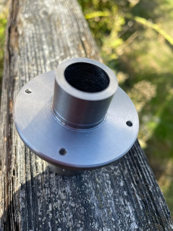
The stand can be bolted to the floor to prevent lateral movement if/when a drive gets out of balance, but will allow vertical movement. The gimbal motor is mounted on top, and the carousel bolted directly to it.
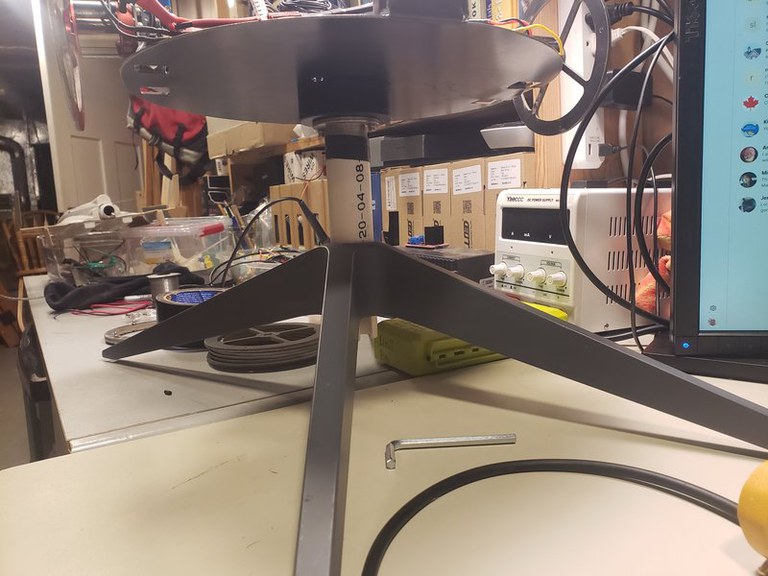
This is a 4 legged frame, the legs of which will be secured to the floor. The PVC pipe/shaft is free to move vertically but cannot rotate due to a key and slot. By placing a load cell (or scale) at the bottom of the shaft the weight of the RV Drive can be measured and recorded.
Load cell.
While a simple scale will be used initially, a 10GK load cell was ordered for aparent weights data logging in future tests. Digital Load Cell Weight Sensor HX711 AD Converter Breakout Module
Logging and graphing the three velocities and load cell.
Realtime logging of Flywheel and Carrier velocities and torque should be possible through the SimpleFOC libraries and the integrated ESP32s to a server.
Similarly the load cell can be monitored through the ESP32 that is is used to drive the Carrier.
Eventually I would like to use ESP32-Now to connect the ESP32 on the MKS Dual FOC V3.3 that drives the carousel and the ESP32 on said carousel that drives the flywheels. This is to facilitate a single control console and to pass data to a logging server. The intention here is to provide real time graphing of the main variables we are interested in:
- Flywheel 1 velocity
- Flywheel 2 velocity
- Carrier velocity
- Apparent weight.
With accurate speed control and real time graphing we hope to investigate the relationships between them. The casual observation available to us in the Marks I and II suggest there is a threshold where "strange things happen". It is our intention to identify what this threshold is and what is actually going on in our first two attempts.
Mock up of the Mark III
This was an early concept. Much has changed since then. This was toying with the idea of two sets of flywheels. The initial test will be only one set like the previous versions.
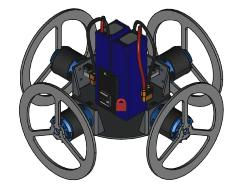
Carrier Plate
The rotor side of the gimbal motor is bolted to the frame and is actually stationary. The Carrier Plate screws to the stator side of the gimbal motor and rotates with the rest of the assembly including flywheels, motors, batteries and electronics.
This first iteration is designed to test flywheels with both a 30 degree Flywheel Lift Angle and fixed flywheels having a 0 degree Flywheel Lift Angle
This is what the device looks like as of August 2005.
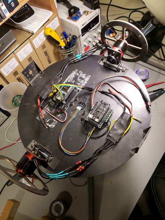
I am getting close to a test run.
Tasks remaining:
- Accurate control of the gimbal motor driving the carrier plate. I am having issues with the Closed Loop control using an AS5048 and SimpleFOC. I hope to have this resolved soon.
- Change the webpage for the controller to use Websockets. Currently I refresh the entire page every RPM update on the flywheels and this is proving so inefficient as to impact performance of the flywheel motors
- Add a Load Cell to measure and log Apparent Weight. I may go ahead with just using a kitchen scale for this test.
TEST RUN
I completed the control system using WebSockets. The test run did not reach the speeds required. The gimbal motor is not driving properly. While it does turn the carrier with velocity values reported, it is at an inconsistent velocity. It speeds up and slows down as it performs each revolution.
I need to tune it using SimpleFOC Studio I think.
DESTROYED BEARINGS
After (mostly) resolving the SimpleFOC control I ran a test. Instead of spinning the flywheels up to maximum first time then rotating as we did with the Mark I that had the initial "interesting" result that appeared to have a 30% weight reduction.
This time I thought to be more methodical and that in turn seems to have been the cause of this failure.
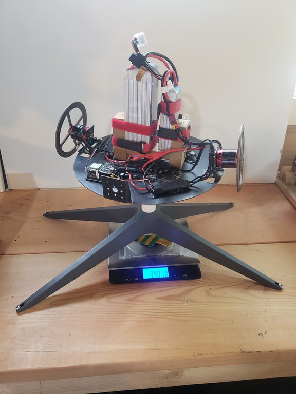
Here is a description of the hardware:
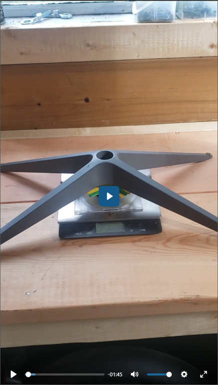
And here is a description of the start up procedure:
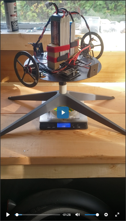
The first time I ran this test I spun the carrier up to 240 RADS/sec without running the flywheels.
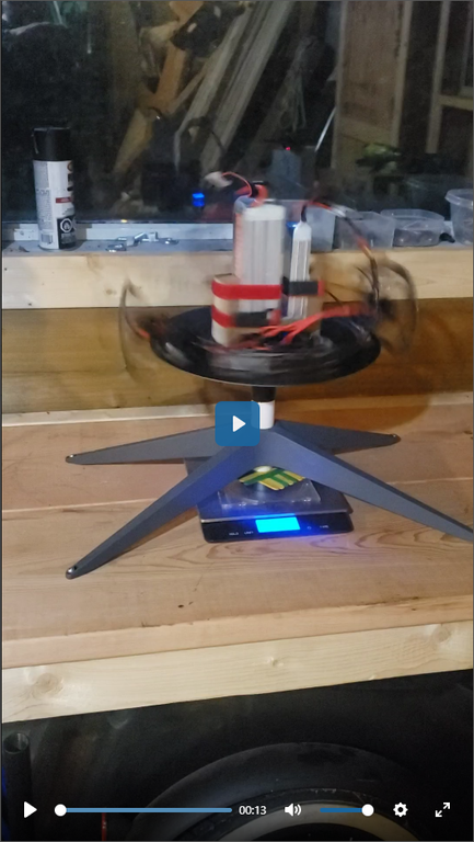
The entire thing rotated relatively smoothly. As one would expect there is little to no variation in the apparent weight.
Even at low disk speed, the flywheels do their thing where they lift, in the next video you can see the flywheels have lifted to their upper position, and there is a high pitched ringing noise that I believe was being caused by load on the motor bearings. Even with the flywheels spinning the system appeared stable, without any great imbalance observed.
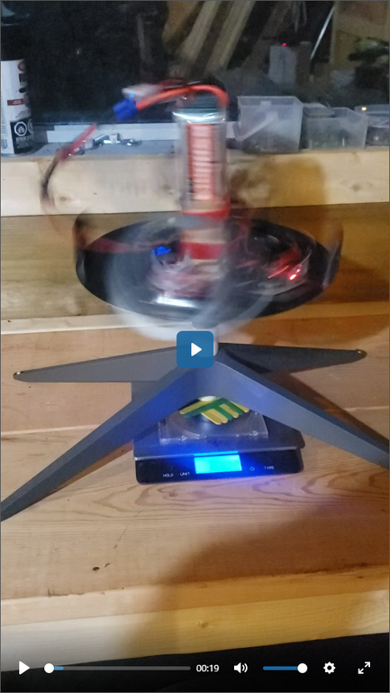
but the entire system was so out of balance that I could not get a decent reading on the scale.
As I increased the speed of the flywheels (disks) there were audible changes in the system, again it seemed to be under some kind of load, then I smelled burring and shut it down. The bearings on one of the flywheel motors has been destroyed and the motor was hot.
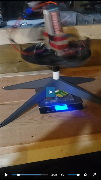
I replaced the motor and repeated, only to repeat an identical failure, the bearings on the flywheel motor being completely destroyed, again without being able to read the scale due to the imbalance and a wildly fluctuation reading on the scale.
Conclusion
I had considered the test a failure and was about to give up and declare the assertion "debunked" but Bjorn is of the opposite opinion, that the destroyed bearings are actually a sign of lift forces being applied.
Consider; the carrier is rotating at it's maximum 240 RADS/sec:
When not spinning the disks
- the carrier rotates smoothly
- the system is rather quiet,
When spinning the disks at slow speed,
- there was slightly more imbalance than when the disks were stopped.
- the spinning disks had a slight whining noise they do not exhibit at the same speed when the carrier is stopped
This implies
- unequal forces on each side of the carrier
- some force is experienced due to the disk spin
- the force is applied differently to each side of the carrier.
when spinning the disks are at higher speed
- the imbalance increases significantly
- the noise of the flywheels increased notably
this implies:
- more force on the motor bearings creating the noise
- even greater unequal forces on each side of the carrier
- there is a vertical component to the forces experienced
The fact that the motor bearings were being chewed out in the same manner even after replacing them suggests there is some force being applied to them that puts them under load for which they were not designed to handle.
At this juncture it would seem that all the forces are contained within the system, and no resultant force was observed or recorded, however SOMETHING is happening that is destroying the motor bearings. I am hitting a wall at certain speeds, and even if no net force is ever achieved, I am determined to see what is on the other side.
Bjorn has convinced me to continue the investigation with the Mark IV....
We will need:
- much stronger bearings, possibly thrust bearings
- better carrier layout, perhaps laying all components out considering their respective weight x distance (moment)
- data logging.
flywheel speed
carrier speed
apparent weight
If there is a threshold to discover we will need to know exactly what s happening.