Mark II
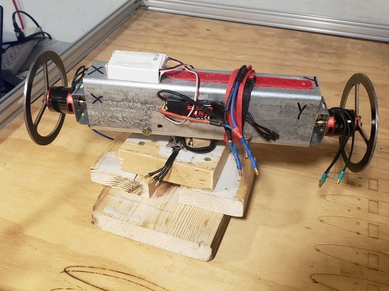
The Mark II major changes.
- modified the carousel shaft mount with a more stable design featuring greater separation between inner and outer carousel shaft bearings and the addition of a third centrally mounted bearing.
- changed the carousel shaft motor to a lower KV rated motor for more torque at lower speeds
- upgraded the Mark I's potentiometer based flywheel speed control to wireless by using ESP32 PWM signals to drive the hobby ESCs and brushless motors using a Bluetooth phone app.
Modified carousel shaft mount
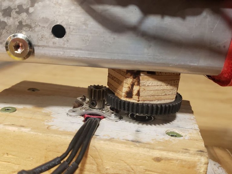
The three inch high carousel mount was increased by 50% to 4.5 inches, literally by screwing on another 2x4 and mounting the new motor with it's top flush with the top of the mount. A hole in the mount allowed me to mount the drive motor below the top bearing.
 motor mounted below the crown and pinion
Replaced the RC hobby speed controllers with a ESP32s.
My original thought was to use my RC plane controller for wireless control of the carousel, but I could not get my RC receivers to bind to my controller. I had some ESP32s on hand so instead used one of those using a PWM signal to the ESC controlled by a potentiometer.

Updated flywheel control.
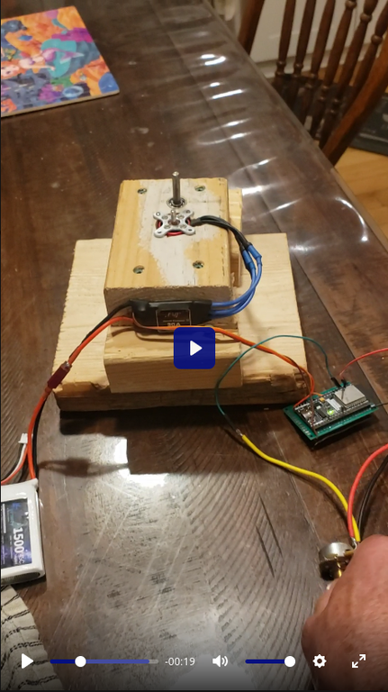
We also replaced the Speed controller for the flywheels with ESP32 based PWM for wireless control via a "Dabble" Bluetooth app. We originally assumed that if we feed the same PWM control signal to a pair of "identical" motors that we could expect identical flywheel speeds. This is what we did in the Mark I but the motors did not actually spin at the same speed. For the Mark II we decided to give each motor individual, discrete control. Again we used hobby ESCs but this time they were fed by the ESP32 PWM. This is what it looked like before adding a LiPo battery:

The white cardboard box on the top contains the ESP32.
Coding the motor control.
The ESC's need three wires connected, +5V, Ground, and PWM signal. That makes it very easy to control via the ESP32, just define a pin for the PWM signal out. I used the Dabble libraries and code for the rest. You can see the code here.
First (and only) test.
I was at first very disappointed in this test. I believe that the reason the Mark I experienced radical imbalance is because each flywheel is indeed experiencing a lifting force, and that force is proportional to the flywheel's speed and rate of rotation. Until that threshold is reached there is no "lifting effect" and imbalance is not experienced. Because of this we started the tests with low sped flywheels (can't find the video of this, sorry). When the flywheels were stopped or spinning slowly nothing of interest happened. The flywheels did not appear to experience any "load", they did not slow down, and the weight registered on the scale did not change. I was quite disillusioned to be frank, and I said to Bjorn:
"Lets just crank it."
Things again got weird.
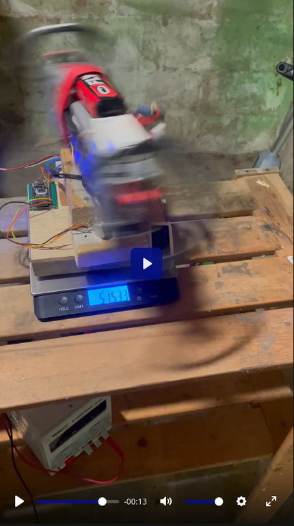
 Mark II test
It seems that when the threshold is reached however things start to happen that are worthy of further investigation.
The two flywheels had nothing to keep them synchronised for speed, and just like the Mark I, when the flywheel speeds got high the entire device became radically unbalanced.
Conclusion
Once again - inconclusive but exciting results. This test convinced me that each arm of the carrier was experiencing something different to explain that insane imbalance. However this test did NOT appear to show any apparent weight change whatsoever.
We decided that we needed to tie the thing down to physically prevent the imbalance from throwing the rig around. A complete rethink and redesign was required. My mission had changed from debunking to investigating.
Changes needed.
- Secure the entire test rig tot he ground.
- Accurately control and synchronise the flywheels
- Accurately control the carousel rotation
Next: The Mark III