Amihan — 42-foot Launchable Glider
A human-launchable 42-foot glider built on Vancouver Island.
The Amihan 42 is a glider concept that is making it's way from my head to these pages as a practical engineering project.
The Amihan Glider Project
Amihan is the Northeast trade wind in the Philippines. It is the summer prevailing winds that give you a steady onshore flow that is great for beach soaring or wind surfing on the east facing coastlines. The Habagat is the Southwest monsoon that brings the rainy season.
The Amihan glider concept developed from daydreaming of soaring the warm winds on the beaches of Negros Occidental Philippines. As the wind comes over the beach it rises up over the sand dunes and other obstacles creating a narrow band of lift that a glider could take advantage of. The beach often provides a convenient launch and landing area. The pilot who is skilled enough to fly within the confines of the standing wave of lift and the strand can fly all day and land anytime for lunch or rest, finds himself in a heaven of low and slow flight in some of the most beautiful places on Earth.
This idyllic mode of flight also has some pit falls which the Amihan project strives to overcome: low and slow.... these are things the dangers of which have been drilled into every pilot since crashing became a thing. Dune soaring combines slow flight, low altitude and turning to stay in the lift band. Ordinarily this is a recipe for disaster because flying close to the stall speed and then turning can quickly put you into the dirt.
With the original dune soaring gliders being flexi wing hang gliders with forgiving stall characteristics, low stall speeds and a prevailing wind that is often higher than the gliders stall speed gives the skilled pilot the ability to turn without steep banking and being almost stationary over the ground. Control was by weight shift and thereby no air disturbances from control surfaces. The Amihan is rigid wing glider with control surfaces although still foot launch able. This presents some challenges: after launching by foot you will be airborne without your feet on the rudder pedals meaning that you will initially not have any rudder yaw control. Ailerons provide banking but simultaneously cause adverse yaw – bank left and yaw right. To mitigate these issues ailerons were replaced with a spoiler on each upper surface near the wing tip as the left spoiler will drop the left wing and cause a bit of drag to yaw the wing in the direction of the turn and the same on the right, allowing the pilot to turn without using rudder. After launch the pilot puts his feet on the rudder pedals which can then be used for slips and coordinating turns.
There is still the issue of stalling during low speed turns. At first wing slots and stall fences were selected, but even though slots do mitigate tip stalls and soften stall behaviour, they are passive. After some thought and observation of the Helio Courier, slots were replaced with aerodynamically controlled slats, two per wing for the entire span. This creates active stall mitigation and allows full length Fowler flaps which become important for low speed flight when deployed to 10 degrees, and lowers landing speeds when at 25 and 40 degrees.
The challenge for a rigid glider is performance range. Rigid gliders usually fly a lot faster than flexi wings, so bringing the stall speed down to 31mph clean and 15mph with flaps coupled with a 15mph wind brings the glider back into the manageable range for beach soaring and foot launch.
Design choices.
The original Amihan glider concept began with the desire to fly in the simplest way, with everyday materials. Its is evolving into a much more refined and technically advanced craft out of necessity because of the constraints of the design goals and choices. To build a glider with a 42 foot cantilever wing, complex controls and sleek appearance with a gross weight of only 385 lbs as well as some demanding performance specs is a tall order. But I think that with today’s space age materials and some careful engineering we are up for the challenge.
Even though an attempt is being made at a sleek appearance, some simpler and cruder elements remain such as a rectangular wing plan rather than the more difficult tapered wing.
The wing has gone through a few iterations: solid foam with a central spar and e-glass skin to an integral spar moulded skin to moulded carbon skins with an e-glass veil central composite spar and foam core ribs and stringers. Carbon fibre is very expensive, but has has the performance and weight characteristics that the design constraints demand.
Some questions are still being explored with regard to the placement of the spoilers: should they be just ahead of the camber aft of the slat for maximum lift spoiling or would it be adequate to place them just ahead of the flap as a lift dump similar to a Boeing or Airbus wing. Then there is the question of slat deployment geometry and angle for best performance and automatic deployment as the wing approaches the stall. These things will have to be tested empirically with a test wing section that will be mounted to a car. Angle of attack and flap angles, slat deployment and stall angle can all be observed and recorded to verify that we are achieving performance goals. Stall speed calculations with flaps up have been made. The theoretical clean stall speed at gross weight is 31 mph, theoretically slats and flaps can increase lift near the stall by as much as 60%. We will confirm these figures with physical tests to define actual performance.
Slats will roll forward on rails while being governed by a torque tube situated in the wing behind the slat and connected with link rods. The slat is free to move on its rails, the forces that affect it will be the relative wind in flight, and forward progression of low pressures when approaching stall speed. The torque tube follows the slat without bias and forces both ends of the slat to advance evenly. The slat is free to move in or out as the flight pressures dictate.
The fuselage will be a semi monocoque design cored composite. The core initially was intended to be half inch thick EPS with e-glass inside and out with some reinforcements at strategic locations such as bulkheads in high stress areas like spar carry through attachments and landing gear and tail. The foam core has metamorphosed into light weight red cedar strips for ease of construction and denser core still with glass inside and out. Wing spar stubs will socket into the spar carry through making the wings removable. The canopy will be heat formed polycarbonate, opening forward to allow the pilot to stand up for launching.
Tail surfaces comprise a vertical fin and rudder, and a stabilator with a trim-able anti servo tab. The position of the horizontal stabilator in relation to the vertical stab and the empennage is quite critical in terms of spin recovery: in a spin the horizontal surface could blank out the vertical rudder rendering the rudder ineffective in spin recovery. Positioning the stabilator at the end of the fuselage allowing the rudder to be somewhat forward puts the wind shadow aft of the rudder for better effectiveness. The choice of a stabilator is to reduce weight and better pitch authority to compensate for full span flaps.
Tail surface area and span has yet to be determined to balance control authority and stability in various flight conditions such as full flaps.
A full scale wing spar needs to be built and tested to destruction to determine if the desired load factor and torsional rigidity measure up in reality. A minimum flight load factor of +3G and -1.5G would be acceptable for ordinary flight, but +-4G is desired. The test would be conducted with a centre section jig to mount the wings to and then to place a distributed span wise load. Of particular interest is the stress riser where the spar exits the carry through socket. Torsional rigidity will be improved by the carbon fibre triaxial fibre orientation in the skins and spar webs as well as a root anchor point near the leading edge.
Amihansketch.JPG
by Bjorn Lampson — last modified2023-08-06T23:35:56+00:00
 Click to view full-size image… Size: 87.0 KB
Amihan 42 foot launchable glider
by Bjorn Lampson — published2022/11/20 20:48:00 GMT+0, last modified2023-08-06T23:50:39+00:00

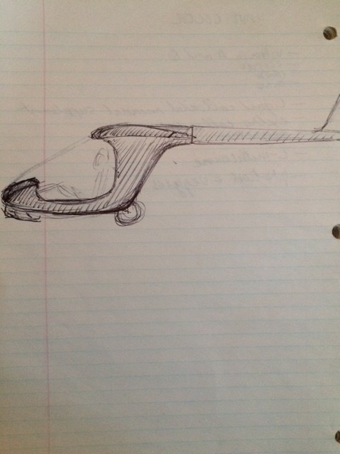
- The Amihan 42 will be a single seat high wing foot-launchable glider that could compete in the high end hang glider category. It will have three axis controls, stabilator for pitch control, fin and rudder for yaw, and spoilerons for roll and yaw during launch as your feet will not be on the pedals at that time. For take off the full span slotted flaps will be at 10 degrees, with an optional setting of 25, and 40 degrees for landing. To manage low speed flight close to stall, there will be a stall fence at the outer 75% position of each wing and a leading edge slot from the stall fence to the tip. The spoilerons will be just aft of the leading edge slots to manage roll control at any speed. Spoilerons will also slow down the inner wing in turns eliminating adverse yaw.
- With a gross weight of 385 lbs and a target stall speed of under 20 mph I envision the Amihan 42 to be ideal for beach soaring or dune gooning. Beach soaring usually has a good steady sea breeze and enough space to soar the shoreline and land back at the launch site. Beach soaring requires precise flying and positive control response.
- Specifications:
- wing span 42'
- chord 4'
- length 20'
- empty weight 100 lbs
- gross weight 385 lbs
- stall speed 20 mph no flaps
- flap range 10*, 25*, 40*
- Other ideas for inspiration and comparison
- Klingberg wing https://www.youtube.com/watch?v=fSp2kP9DTbM
- Archaeopterex https://www.flixxy.com/foot-launched-glider.htm
- Arnes http://www2.arnes.si/~cetim6/fls1.htm
- Carbon Dragon http://www.carbondragon.us/
- Super Floater https://www.youtube.com/watch?v=qO35z9cElVo
- Arienne Swift https://www.flymanilla.com/Equipment/SWIFTLITEULGlider/tabid/344/Default.aspx
- Atos https://www.aeroexpo.online/prod/air-gmbh/product-171220-2809.html
updated sketch
by Bjorn Lampson — last modified2023-07-30T03:46:51+00:00
 Click to view full-size image… Size: 26.0 KB
by Bjorn Lampson — last modified2023-07-30T03:46:51+00:00
 Click to view full-size image… Size: 87.0 KB
Amihan 42 Control System
by Bjorn Lampson — published2022/11/20 16:34:00 GMT+0, last modified2023-07-30T03:46:51+00:00Contributors: 075d4981eb3a43609203f823cd548271
Flight controls will be with a side stick (RH side) and rudder pedals. Flap lever will be on the left side 10* for take off, 25* and 40* for landing. Stabilator control will be with carbon fiber push-pull tube. Rudder will have two cables. Spoilerons will have a single carbon fiber pull tube in each wing, and flaps will use a single carbon fiber torque tube in each wing. Stabilator will have an anti servo tab for pitch stability and trim.
Contents
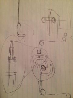
Cam plate to control spoilerons to eliminate nul point slop

Flap Mechanism
by Bjorn Lampson — last modified2023-07-30T03:46:51+00:00
 Click to view full-size image… Size: 28.0 KB
IMG_0459.JPG
by Bjorn Lampson — last modified2023-07-30T03:46:51+00:00
 Click to view full-size image… Size: 10.0 KB
sawhorse.JPG
by Bjorn Lampson — last modified2023-07-30T03:46:51+00:00
 Click to view full-size image… Size: 59.0 KB
ribs.JPG
by Bjorn Lampson — last modified2023-07-30T03:46:51+00:00
 Click to view full-size image… Size: 52.0 KB
building plug.JPG
by Bjorn Lampson — last modified2023-07-30T03:46:51+00:00
 Click to view full-size image… Size: 45.0 KB
plug.JPG
by Bjorn Lampson — last modified2023-07-30T03:46:51+00:00
 Click to view full-size image… Size: 38.0 KB
plug2.JPG
by Bjorn Lampson — last modified2023-07-30T03:46:51+00:00
 Click to view full-size image… Size: 34.0 KB
16916446157397090640587613802482.jpg
by Paul O'Rorke — last modified2023-08-10T05:17:55+00:00
 Click to view full-size image… Size: 3.0 MB
20230810_001653.jpg
by Paul O'Rorke — last modified2023-08-10T15:38:54+00:00
 Click to view full-size image… Size: 3.0 MB
20230810_001659.jpg
by Paul O'Rorke — last modified2023-08-10T15:38:55+00:00
 Click to view full-size image… Size: 3.0 MB
20230810_001725.jpg
by Paul O'Rorke — last modified2023-08-10T15:38:57+00:00
 Click to view full-size image… Size: 889.0 KB
20230810_001731.jpg
by Paul O'Rorke — last modified2023-08-10T15:38:59+00:00
 Click to view full-size image… Size: 759.0 KB
20230810_001744.jpg
by Paul O'Rorke — last modified2023-08-10T15:38:59+00:00
 Click to view full-size image… Size: 3.0 MB
20230811_065937.jpg
by Paul O'Rorke — last modified2023-08-11T18:44:10+00:00
 Click to view full-size image… Size: 874.0 KB